
Simple Ways to Plan Your Automation Today So It Can Grow Tomorrow
Nobody knows exactly what a plant will need five or ten years from now. Another pump may be added. Production may increase. A remote site may come online. Operations may want more data. An older piece of equipment may finally need replacement.
You cannot design for every possibility, but you can avoid designing yourself into a corner. A few practical decisions during the original project can preserve useful options when the first expansion arrives.

Plan for options, not predictions
Future-ready design does not mean buying equipment that may never be used. It means considering physical space, electrical capacity, communications, programming structure, and documentation while changes are still inexpensive to accommodate.
The goal is simple: make the next addition an extension of the system, not a reason to redesign it.
Six decisions that make growth easier
1. Leave some room
A panel filled from top to bottom on day one offers few good expansion options. Consider spare DIN rail, usable wireway space, power supply capacity, heat load, and a reasonable amount of spare I/O.
Outside the panel, consider whether extra conduit, pull space, or fiber capacity can be installed economically during construction.
2. Build a network
Think beyond a collection of individually connected devices. Consider where another PLC, VFD, remote I/O rack, HMI, or instrumentation network could fit and how traffic, addressing, security, and remote connectivity would be managed.
3. Use standards early
Consistent PLC tags, device names, IP addressing, wire numbers, alarm conventions, and equipment numbering may seem excessive on a small system. They become valuable as the number of controllers, devices, and people grows.
4. Keep logic understandable
Organize control logic by equipment or process function. Use meaningful names, understandable sequences, and clear interfaces. Avoid unnecessary dependencies between unrelated parts of the system.
5. Keep documentation alive
Electrical drawings, network diagrams, I/O lists, PLC comments, HMI documentation, and equipment settings should change when the system changes. Documentation is part of the control system, not an optional record created at the end.
6. Choose flexibility where it matters
When two reasonable equipment choices exist, ask whether the device can communicate with likely future systems, accept another module, expose useful data, and remain supportable through the expected lifecycle.
Turn expansion into an architecture question
Before selecting components, sketch how the system could change. Where would added I/O connect? Which switch port, enclosure, power supply, controller resource, and network segment would support it? Would operators need another HMI view? Who would update backups and drawings?
This exercise does not lock the plant into one future. It reveals low-cost provisions that preserve several possible futures.

A practical planning review
Physical capacity
- Is there accessible rail and wireway space?
- Can the enclosure manage added power and heat?
- Are conduit, cable tray, and fiber routes expandable?
- Can future work be completed safely around operating equipment?
Control and network capacity
- Is spare I/O appropriate for likely additions?
- Are controller, HMI, and network resources understood?
- Is the addressing and naming plan documented?
- Can remote sites or new equipment be segmented appropriately?
Lifecycle capacity
- Are programs and configurations backed up?
- Do drawings and device lists match the installed system?
- Can another engineer understand the code and sequences?
- Are platform support and migration considerations recorded?
Do not confuse spare capacity with an engineering decision
Available panel space, I/O, network bandwidth, or controller memory does not automatically make an addition suitable. Each change still needs application review, electrical and thermal checks, network and cybersecurity consideration, and any required safety or code evaluation.

Make the handoff usable
Future expansion often happens years after the original project and may involve a different engineer, integrator, or maintenance team. A clean program structure and current documentation give that team a reliable starting point.
Record not only what was installed, but also the conventions used, reserved addresses, spare capacity, known limits, and decisions that may affect later work.
The bottom line
Future-proofing automation is not about predicting the future. It is about making sure the future still has options.
Leave practical room, create an expandable architecture, use standards before they feel necessary, write logic another person can follow, keep documentation current, and choose flexibility where it has real application value. Those decisions can turn a disruptive redesign into a manageable expansion.
How can BEA help?
BEA helps industrial and municipal facilities plan control panels, PLC and HMI platforms, industrial networks, remote I/O, standards, documentation, and phased modernization. We can review current requirements alongside likely growth scenarios and help identify practical provisions without overbuilding the first project.
For an example of a scalable control and information framework, see Rockwell Automation's Integrated Architecture overview.
The Hidden Cost of Deferred Maintenance in Critical Infrastructure
A raw water pump runs 600 hours past its grease interval. A PLC low-battery alarm is acknowledged and forgotten. A control-panel exhaust fan keeps rattling on worn bearings.
None of these conditions stops the plant today, so each can appear easy to postpone. The cost does not disappear. It moves downstream, where it is often more expensive and harder to control.
Planned work costs less than reactive work
1. Scheduled maintenance
Parts, staffing, downtime, backups, and operating coordination can be arranged before work begins. The interruption is expected and controlled.
2. Deferred servicing
Wear continues, cooling declines, connections loosen, batteries lose capacity, filters load, and nuisance trips appear. The asset still runs, but its reliability margin is shrinking.
3. Emergency failure
The facility now faces an unplanned outage, emergency labor, expedited freight, temporary procedures, production loss, or damage beyond the original maintenance item.
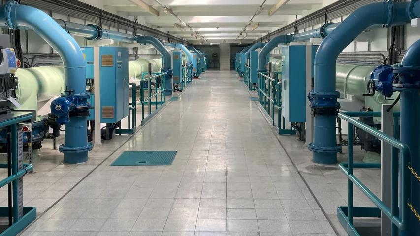
Where hidden costs live
A maintenance backlog rarely appears as one clean expense. It spreads into the surrounding equipment, supply chain, staff knowledge, recovery plan, and operating risk.
The original task may be inexpensive. The consequences of waiting may not be.
Collateral damage
A failed panel fan can expose a VFD, power supply, or PLC enclosure to excess heat. A leaking seal can affect nearby wiring or instrumentation. A loose connection can damage terminals, conductors, breakers, and enclosures.
Supply-chain exposure
PLCs, VFDs, safety devices, communication modules, and breakers may have long lead times or limited availability. Older components may be available only through surplus channels or brokers.
Lost institutional knowledge
Undocumented operating sequences, drive settings, logic changes, and recovery steps leave a facility dependent on the continued availability of particular people.
Safety and regulatory margin
Ignored alarms, degraded instruments, missed calibrations, and poorly maintained protective devices can reduce margin until several small problems align at the wrong time.
Recoverability is part of maintenance
A control system can operate normally and still be difficult to recover. A missing PLC backup, an HMI project stored only on an old laptop, unsaved VFD parameters, outdated network records, or inaccurate electrical drawings may not affect today's production. Each missing item can add hours or days after a failure.
Redundancy has to be maintained too
Two pumps, standby equipment, backup generators, spare drives, redundant communication paths, and shelf spares only reduce risk when they are ready to work.
Exercise it
Run standby pumps, test backup power, and verify alternate communication paths on a planned schedule.
Inspect its condition
A backup VFD in fault or a generator with a weak starting battery provides little protection during an outage.
Keep it deployable
A spare PLC without the current program is only hardware on a shelf. Store the software, parameters, cables, licenses, and instructions required to put spares into service.
Age alone does not define reliability
Older equipment can remain dependable when it was installed correctly, maintained properly, documented, and supported with usable spares. Newer equipment can create problems when it is overloaded, poorly installed, exposed to excessive heat, or neglected.
Ask risk-based questions
- Can the equipment still be supported, and are replacement parts available?
- Is there a tested, usable spare?
- Are PLC and HMI programs, drive parameters, and drawings current?
- Does more than one person understand how the system operates?
- What happens to the process if this asset fails?
- How long would a safe recovery take?
Why the backlog builds
Visible projects win budgets
Capital improvements are easy to identify, while routine maintenance competes quietly with other funding needs.
Running gets confused with reliable
Equipment can continue operating while its reliability margin steadily decreases.
Staffing stays reactive
Preventive work is often postponed when limited maintenance staff spend most of their time on current problems.
Deferred work loses ownership
Tasks held in notes, emails, or memory are difficult to prioritize and easy to forget.
Breaking the reactive cycle
Audit the critical path
Prioritize assets whose failure could stop the process, create a safety concern, eliminate redundancy, or require a difficult recovery.
Standardize practical spares
Where practical, standardize frequently replaced power supplies, relays, contactors, fuses, cooling fans, UPS batteries, and communication hardware. Verify that every spare fits the intended application.
Upgrade incrementally
Create migration plans for equipment with poor supportability, unavailable parts, missing backups, or serious process consequences. Planned modernization is easier to control than emergency modernization.
Protect the schedule
When work must be postponed, keep it visible, evaluate the consequence, assign ownership, and set a new date instead of allowing it to disappear.
The bottom line
Deferred maintenance can look inexpensive while equipment is still running. Its real cost appears later through reduced reliability, emergency labor, collateral damage, missing spares, difficult recovery, and operational risk.
Good maintenance cannot guarantee that nothing will fail. It makes failures more predictable, recovery more manageable, and emergency decisions less common. Reliable facilities deal with small problems while they are still small.
How can BEA help?
BEA helps water, wastewater, and industrial facilities assess control-panel health, plan PLC and HMI lifecycles, review backups and documentation, troubleshoot control systems, and build preventive maintenance strategies around the equipment and processes that keep the facility operating.
Why I Show Up to City Council Meetings as an Engineer, Not Just a Resident
Most people who show up to a city council meeting are there for something that directly affects their neighborhood. I tend to notice the four-minute agenda item almost nobody else in the room fully understands.
A line item approving remote access upgrades at the water plant. A vendor change for the SCADA system that runs it. A communications upgrade between a well site and the treatment plant.
Those items can move fast. They are scheduled between a parking ordinance and a parks budget update, and sometimes they pass without a single technical question. That is the part that gets me in the car.
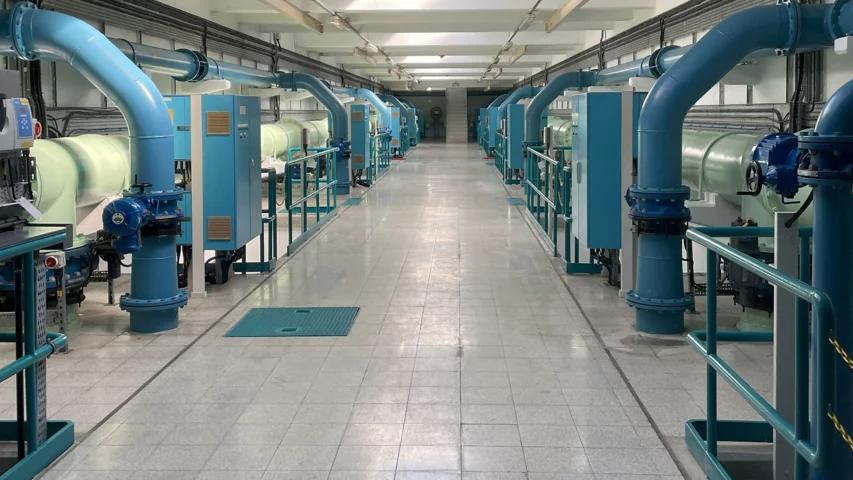
Water treatment plants depend on coordinated pumps, controls, communications, and secure support practices. Image: Rockwell Automation.
The Four Minutes Nobody Understands
When remote access comes up, the useful questions are practical. They are the same questions a control systems engineer should ask before signing off on a project.
Council members weigh budgets, policy, priorities, and community needs. They are not expected to evaluate industrial network architecture. Plant personnel may be operating an entire utility with limited staffing. The vendor is there to propose and deliver a system. Independent technical scrutiny still matters.
Identity and access
Does remote access require multi-factor authentication? Who has access, and how is that access removed when a person or vendor no longer needs it?
Network path
Where does the connection terminate? Does it land on a controlled jump host, or create a path toward the network communicating with PLCs?
Lifecycle support
Will the vendor still support the HMI or SCADA software five years from now, or is the municipality buying a difficult migration for 2031?
These are not exotic questions. Yet in a council chamber, nobody may have the specific job of asking them. Sometimes the questions simply do not get asked. They cost nothing to ask in the room, and they can cost a great deal to skip.
What Skipping Them Can Cost
In July 2026, Minnesota officials reported malicious cyber activity targeting technology at more than 30 community water systems. Most confirmed cases involved technology used to remotely monitor or control equipment.
That is why the architecture behind remote access matters. The answer is rarely as simple as buying a better firewall after something happens. The better starting point is months or years earlier, when someone asks how access is designed, who will maintain it, what protections are in place, and what happens when a component fails.
By the time an infrastructure system appears in an incident report, the decision that mattered may have been made long before. Sometimes it was part of a five-minute agenda item that nobody thought needed another question.

Automated pumping and treatment equipment depends on reliable controls, communications, and support practices. Image: Rockwell Automation.
This Is Not About Slowing Anything Down
I am not at these meetings to embarrass anyone or throw sand in the gears of a project that has already been properly vetted.
Most of the time, the answer to my question is perfectly reasonable, and the meeting moves on exactly as it would have anyway. I am there because I understand what is actually being decided.
Evaluating remote access architecture is not something most residents are expected to do. It is what I do professionally.
What Technical Residents Can Contribute
Listen for operational technology
Notice agenda items involving SCADA, HMI, PLCs, telemetry, cellular communications, remote support, or vendor access.
Ask one clear question
Focus on an important control such as MFA, segmentation, access removal, logging, fallback operation, or long-term support.
Respect the room
The goal is to improve a decision, not perform a technical cross-examination. A concise question can reveal whether the issue has already been addressed.
If you are an engineer, IT professional, operator, or someone who has spent time around OT systems, sit in on a city council or utility board meeting sometime, even if you only watch.
You may be surprised how many real infrastructure decisions are made in a matter of minutes by people who may never personally see the equipment they are approving money for.
Showing up does not fix everything. But it can mean that at least one person in the room asks the question before it becomes an incident report.
Further reading: Minnesota IT Services update on community water system cyber activity and CISA and EPA guidance on internet-exposed HMIs.
VNC vs. HTML5 Web Clients: Choosing the Right Remote Interface for HMI/SCADA
Remote HMI and SCADA access can help an operator check a process from another building, let a technician watch a pump while standing beside it, or allow an integrator to troubleshoot without an immediate trip to the site. Two common interfaces are VNC and an HTML5 web client. Both can work well, but they are built for different jobs.
The most useful question is not which technology is newer. It is what a particular person needs to see, control, and troubleshoot.
Start with the secure access path
Neither VNC nor an HTML5 HMI/SCADA client should be exposed directly to the public Internet. Remote access should begin with a properly secured and maintained VPN or an equivalent controlled remote-access architecture.
The secure connection answers how the user enters the environment. VNC or HTML5 answers what that user can reach after entry. Reaching the VPN should not automatically provide access to every PLC, HMI, switch, server, and engineering workstation. Network segmentation, firewall policy, named user permissions, logging, and time-limited vendor access should narrow the path to the work being performed.
Two interfaces, two operating models
VNC: share the actual workstation
VNC typically shows and controls the session already running on an HMI computer. The local operator and remote specialist may see the same screen, cursor, values, and screen changes.
This shared view is valuable when a technician or integrator needs to observe a problem, inspect HMI diagnostics, check communications, restart an application, or investigate the workstation itself.
HTML5: use the HMI through a browser
An HTML5 client presents process screens, alarms, trends, setpoints, history, and approved controls in a browser. The user can work with the HMI application without necessarily receiving access to the computer underneath it.
This separation is useful when an operator needs process visibility or approved control from a laptop, tablet, or phone, but does not need the Windows desktop or engineering tools.
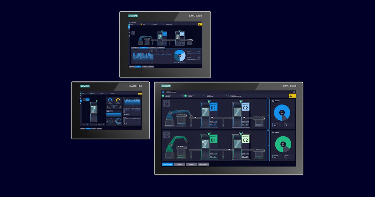
Match the interface to the task
A person checking one value beside a machine may benefit from a focused browser session. A controls specialist diagnosing a workstation issue may need the actual machine session. The role and task should drive the interface choice.
Shared context or independent sessions?
A shared VNC session can make troubleshooting easier because everyone sees the same screen and actions. An operator can reproduce a problem while an integrator watches the same values, changes screens, and explains the next check. The shared session reduces confusion about which display is open or what changed.
Independent HTML5 sessions provide flexibility, but they also require a control-authority plan. Two authorized users may look at the same equipment from different locations without seeing each other's actions. If both can change a setpoint or place equipment in manual, independent access can become an operational coordination problem.
Questions for multiple users
- Who has control authority?
- Can two users control the same equipment at once?
- Which roles should be view-only?
- Can authority be transferred clearly?
- Can users see when remote operation is active?
- Are commands and changes logged by user?
When shared viewing helps
- Reproducing an intermittent operating issue
- Coordinating an operator and integrator
- Reviewing HMI diagnostics
- Confirming the same alarm or process value
- Guiding a local technician through checks
Walk-around access and screen design

Browser access can be convenient when a technician is priming a pump and needs to watch discharge pressure, or when an operator wants to verify a signal while working away from the control room.
However, opening a control-room display on a phone does not make it suitable for phone operation. Tiny buttons, dense graphics, alarm windows, and small entry fields can create usability and safety concerns. If mobile operation is expected, design and test the HMI screens for the intended device and operating conditions.
Practical comparison
| Decision area | VNC | HTML5 web client |
|---|---|---|
| What the user reaches | The actual HMI workstation session | The HMI/SCADA application through a browser |
| Strong fit | Troubleshooting, collaboration, legacy access, workstation-level tasks | Routine process viewing, approved operation, walk-around access, role-focused screens |
| Session behavior | Often shared, so participants see the same actions | Often independent, which supports concurrency but needs authority rules |
| Device experience | Mirrors the workstation display and may be awkward on small screens | Can support multiple device types when screens are designed responsively |
| Access scope | May expose the desktop and more workstation capability than an operator needs | Can keep the user inside the application and approved functions |
| Licensing | May reuse an existing runtime session, depending on product terms | May require web, named-user, concurrent-user, runtime, server, or mobile licenses |
Licensing and growth can change the answer
Check the exact platform license before selecting an architecture. Browser access may be included, or it may require licenses for web clients, named or concurrent users, remote sessions, server features, additional runtimes, or mobile access. VNC may view an already licensed runtime, but that does not make it universally less expensive or permitted in every configuration.
Price the expected future state as well as the first connection. One browser session today can become operators, supervisors, maintenance technicians, engineers, and vendors tomorrow. Ask what the tenth connection requires, not only what the first costs.
Legacy systems still have a place
Some older HMI panels and workstations have no practical HTML5 option. Replacing a reliable system only to add browser access may not be justified. Controlled VNC access can extend supportability when the risk is assessed, the path is secured, and the workstation remains appropriately maintained and isolated.
This is not simply old technology versus new technology. It is a lifecycle and application decision.
Vendor access needs a beginning and an end
Third-party access should be enabled for a defined support task, visible to the responsible facility personnel, limited to the relevant system, and disabled when the work is complete. Permanent unrestricted accounts create avoidable exposure and make it harder to know who can still enter the environment.
Security also has to be workable. Strong authentication and access controls belong at the remote boundary, but the approved workflow should remain usable enough that operators and technicians do not feel pushed toward unsafe workarounds.
Remote access must not become required for local control
Every remote communication path will eventually be unavailable. A VPN, Internet circuit, radio, cellular link, or server may fail or require maintenance. The PLC should continue its local control strategy, and the local HMI should remain available where one is installed. Losing remote visibility should not automatically stop the process.
Sometimes the right answer is both
Operators and supervisors
VPN or controlled gateway to an HTML5 client designed for process viewing and approved operation. Use role-based permissions, view-only access where appropriate, and clear control authority.
Maintenance and engineering
VPN or controlled gateway to time-limited VNC access when technical personnel need the actual workstation for diagnosis or collaboration.
RDP may also be useful in centralized SCADA and engineering environments where users need separate Windows sessions. It solves a somewhat different problem from sharing an existing HMI session or opening a browser client, so evaluate it as a separate architecture choice.
A simple field checklist
- Who is connecting? Operator, supervisor, maintenance technician, engineer, integrator, or vendor.
- What must that person do? View the process, operate equipment, troubleshoot an application, or work on the HMI computer.
- Do they need the application or the workstation? This often separates HTML5 from VNC quickly.
- Should the session be shared or independent? Consider collaboration and concurrent control.
- How is control authority assigned and shown? Define view-only roles, command logging, and transfer rules.
- How many users are expected? Verify current and future licensing.
- What is the smallest safe network scope? Limit routes, protocols, systems, and time windows.
- What happens when communications fail? Preserve local control and a clear operating response.
How can BEA help?
BEA can help assess the operating roles, HMI/SCADA platform, network boundaries, licensing, screen design, support workflow, and local fallback requirements before remote access is implemented or expanded. The goal is not the greatest possible reach. It is controlled, practical access that supports the person and task without weakening plant operation.
For independent remote-access security guidance, review CISA's Industrial Control Systems recommended practices. Product-specific capabilities, license terms, and security requirements should also be confirmed with the applicable HMI/SCADA manufacturer.
BEA Industrial Networking Blog
KISS in SCADA: Why Over-Engineered Networks Create Operational Nightmares
Most industrial network designs look convincing in a presentation. At 2:00 a.m., the measure that matters is whether an on-call technician can identify a failed path, preserve safe local control, and restore telemetry quickly.
Complexity multiplies the fault domain
Layered topologies, nested VLANs, enterprise authentication, redundant rings, SD-WAN overlays, and multi-hop VPNs can each solve a legitimate problem. When stacked without a clear operational need, they create a chain in which one unavailable service or one incorrect rule can interrupt critical communications.
Practical rule: Critical OT communications should remain predictable and operational when enterprise services or wide-area links are unavailable.
Four common ways complexity becomes an outage
1. Enterprise dependency creep
A field switch or controller depends on remote authentication, DNS, certificate, or cloud services. A WAN failure then becomes a local operations problem.
Design response: Keep essential local control independent, and document which external services affect recovery.
2. Segmentation without visibility
Too many zones and rule sets hide the traffic technicians need to diagnose intermittent EtherNet/IP, PROFINET, or Modbus TCP issues.
Design response: Group devices by process function, allow only required flows, and preserve approved diagnostic access.
3. Fragile remote connectivity
Nested tunnels, carrier addressing changes, continuous polling, and manual reconnect procedures make small communications events expensive.
Design response: Support safe local operation, data buffering, automatic reconnection, and efficient reporting.
4. Redundancy that obscures failure
Poorly controlled rings, gateways, and high-availability pairs can introduce loops, duplicate addresses, slow convergence, or split-brain behavior.
Design response: Test failover, define expected recovery time, and keep replacement procedures usable by on-call staff.
Visual contrast: complicated recovery versus supportable recovery
Operational nightmare
- Ownership changes at every layer
- Unknown dependencies on WAN services
- Firewall policy is the only traffic map
- Failover behavior is assumed, not tested
- Replacement requires proprietary expertise
Supportable SCADA network
- Process zones have clear purposes
- Controllers fail safely and operate locally
- Data flows and dependencies are documented
- Recovery is tested under realistic outages
- Backups and preconfigured spares are ready
Segmentation still matters, but it needs an operational purpose
Simple does not mean flat or unprotected. Segmentation remains an important control for limiting access and containing threats. The goal is deliberate zoning with understandable boundaries, not a separate island for every device. Network diagrams should show major connections, allowed data flows, remote access paths, and external dependencies so both operations and incident response teams can work from the same picture.

Remote sites should remain useful when the link is down
Lift stations, well sites, valve vaults, and pumping stations often rely on cellular service. A sound design assumes interruptions will occur. The PLC, RTU, or controller should continue its approved local strategy, buffer important records where appropriate, and reconnect without a truck roll. Protocol choices such as MQTT Sparkplug B, DNP3 exception reporting, or store-and-forward features may reduce traffic and improve recovery, but suitability depends on the application, threat model, and validated system design.
Four KISS rules for reliable SCADA networks
Favor predictability
Use controlled addressing and minimize dynamic service dependencies for critical OT assets.
Prioritize local autonomy
Design PLCs, RTUs, and controllers to maintain approved safe operation during communication loss.
Keep infrastructure supportable
Document and back up configurations. Prepare tested spares and clear replacement steps.
Monitor the boundaries
Build visibility at firewalls, gateways, and remote links before adding custom workarounds.
Questions to ask before adding another layer
- Which specific operational or security risk does this component reduce?
- What happens locally if it or its upstream service is unavailable?
- Can the on-call team see and diagnose the resulting traffic path?
- Has failover been tested with realistic power, carrier, and configuration failures?
- Can a documented spare restore service without specialist escalation?
How can BEA help?
BEA can help review industrial network architecture, map dependencies, assess remote communications, simplify support procedures, and plan tested migration or recovery steps. The target is not the fewest possible components. It is the simplest design that meets the application, cybersecurity, availability, and lifecycle requirements.
Troubleshooting beyond the alarm
A PLC Fault Is Usually the Symptom, Not the Diagnosis
A fever tells you something is wrong. It does not tell you what caused it. A PLC fault works the same way. It is a signal, not an answer. Clear it without understanding it, and the underlying problem may still be there.
The fault is telling the truth
Clearing a fault can restore operation, but it does not prove the underlying condition is gone. The device reporting the problem is not necessarily the device causing it. Good troubleshooting separates where the symptom appeared from where the failure began.
The fault told the truth. It just did not tell the whole truth.
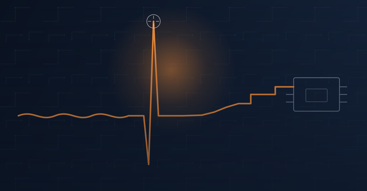
A brief signal transient can reveal itself at the PLC even when the initiating condition began elsewhere in the control system.
Follow the failure backward
Start with the alarm, then trace the conditions that could have produced it. Check the power feeding the circuit, signal behavior, field wiring, communications path, and the process condition the controller expected to see.
The objective is to identify the first abnormal condition, not simply the last device that complained.
A card replacement that did not hold
At one facility, several analog readings began dropping out for an instant, jumping to full scale within milliseconds, then settling back down. The analog input card was the obvious suspect. It was replaced, the fault cleared, and the system returned to service.
A few days later, the same symptom returned on a different card. That recurrence changed the question from "Which card failed?" to "What are these cards seeing that they should never see?"
The actual cause
The 24 VDC field power supply feeding the I/O circuits had begun to degrade. Its output became unstable under load. Those disturbances reached the analog circuitry and produced momentary dropouts followed by full-scale readings.
The event was fast enough to resemble noise on a trend and fast enough that a technician standing at the panel with a meter could easily miss it. Replacing the power supply stopped the problem because the failed component was finally identified.
The same pattern appears across a control system
Drive fault
The drive reports the condition, while the cause may be a mechanical load, unstable input power, wiring issue, or process demand.
Unreliable sensor
The sensor gets blamed, while damaged wiring, poor shielding, electrical noise, or unstable field power may be changing the signal.
Remote I/O dropout
The rack goes offline, while the initiating problem may be a switch, cable, connector, radio path, or upstream power supply.
Controller communications fault
The PLC becomes unresponsive, while malformed, incomplete, or excessive traffic elsewhere on the network may be consuming limited communications resources.
Questions that move the diagnosis forward
- What changed immediately before the event?
- Is control and field power stable under the actual load?
- Are the I/O signals behaving normally at the source and at the module?
- Are field devices communicating correctly?
- Is the network healthy, or merely connected?
- Is the process reaching the position, pressure, level, speed, or state the PLC expects?
- What evidence remains after the fault is reset?
A reset is a recovery step, not a root cause
Replacing the component named in an alarm is not always troubleshooting. A system returning to normal after a reset does not mean the cause disappeared. Preserve event history, capture trends at useful time resolution, and test the full signal and power path before declaring the issue resolved.
How can BEA help?
BEA can help trace intermittent PLC, I/O, power, drive, and industrial network problems across the system instead of stopping at the first alarm. We support evidence-based troubleshooting, application review, component selection, and corrective planning so the same symptom does not keep returning.
Bring us the fault history, trend data, recent changes, and what has already been tested. We will help turn the alarm into a practical diagnostic path.
Industrial Cybersecurity
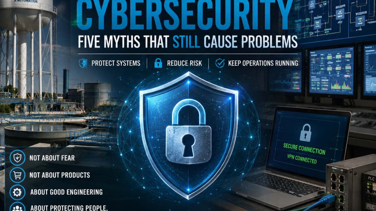
Industrial Cybersecurity Myths We Still Encounter in the Field
The most important improvements often begin with correct network design, clear access paths, and layered protection.
The problem often starts before a security appliance is installed
After a major cyberattack, the first questions often focus on firewalls, software, or the newest security product. Those tools have a place, but many significant improvements cost little. They begin with designing industrial networks correctly and challenging assumptions about how systems are connected.
Manufacturers, municipalities, water systems, and other industrial facilities can take security seriously and still carry hidden risk when trusted devices or support processes create overlooked pathways.
Five myths worth challenging
Myth 1: Our PLC is not connected to the Internet
The PLC may have no direct Internet connection, while an engineering workstation, HMI, remote support computer, historian, reporting server, cloud dashboard, or vendor remote-access package does.
An attacker may only need access to a trusted device that already communicates with the PLC. Map every pathway into the control network, not only the PLC's public exposure.
Myth 2: We have a firewall, so we are secure
A firewall is an important layer, but it is not the complete architecture. Effective protection can include VPN-only remote access, strong authentication, segmentation, least privilege, secure support procedures, logging, monitoring, and routine maintenance.
Design the system so other protections continue to reduce risk if one layer fails.
Myth 3: We are too small to be a target
Small manufacturers, municipal water and wastewater systems, grain facilities, and local industries can all experience cyber incidents. Many attacks are automated and search broadly for vulnerable systems.
Organization size does not remove exposure. Security posture and reachable pathways matter.
Myth 4: Our vendor handles cybersecurity
Equipment, network, and firewall manufacturers can provide capable components, but no single vendor automatically knows how the entire facility is connected.
Security comes from integrating devices, networks, remote connections, engineering workstations, and support processes correctly. That is an engineering responsibility.
Myth 5: Nothing has happened, so we must be secure
Years without a known incident do not prove that the architecture is secure. An exposed path may simply remain undiscovered.
Preventive cybersecurity works like preventive maintenance: remove unnecessary risk before it affects operations.
Good security should support daily work
Operators still need to operate. Maintenance personnel still need to troubleshoot. Authorized engineers still need to provide support. A properly designed system preserves those workflows while preventing unauthorized access.
The objective is not complexity or fear. It is thoughtful engineering: understand communications, limit unnecessary exposure, plan remote access, and build multiple layers of protection around the people and infrastructure that depend on the system.
How can BEA help?
BEA can help industrial teams review network pathways, remote-access practices, segmentation needs, engineering workstations, and support workflows. The goal is a practical security approach that protects operations without obstructing authorized users.
Read the original source article for the full field perspective.