
Control Panel Engineering
Control Panel Cooling: Why Adding a Fan Isn't Always the Answer
Understanding heat loads, airflow, ambient temperatures, and why the right cooling solution starts with understanding where the heat goes.

A fan can move air inside a control panel, but it cannot make heat disappear. Reliable thermal management starts by estimating how much heat the equipment produces, understanding where that heat can go, and selecting a method that still works at the worst expected ambient condition.
The real problem is heat flow, not fan count
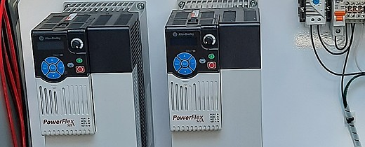
VFDs, power supplies, PLCs, industrial computers, transformers, contactors, and communication equipment all convert part of their input energy into heat. In a densely packed or sealed enclosure, that heat raises the internal air temperature and can create much hotter local zones around major heat producers. For a water or wastewater facility, high room temperature, outdoor sun, a loaded process, or a clogged filter can turn a panel that normally runs well into a summer reliability problem.
Internal circulation
A circulation fan can reduce hot spots, improve temperature distribution, and move heat toward enclosure surfaces or cooling equipment. It does not independently remove heat from the enclosure.
Ventilation
A filtered fan can carry heat out only when the incoming air is cool enough and acceptable to bring into the enclosure.
Closed-loop cooling
A heat exchanger or air conditioner keeps internal and external air paths separate, helping preserve enclosure protection in dusty, oily, or wet environments.
Start with a heat-load inventory
For each component, use the manufacturer's published power-loss or heat-dissipation value at the expected load and duty cycle. Do not treat the connected load as though all of it becomes heat inside the panel. Most power passing through a VFD is delivered to the motor; only the drive's losses are dissipated as heat inside the enclosure.
- List every heat-producing device inside the enclosure.
- Record the loss in watts at the expected operating point, including duty cycle, loading, and simultaneous operation.
- Add the losses to obtain the internal heat load in watts.
- Convert the result to BTU/h when cooling equipment is rated in those units.
BTU/h is a rate of heat transfer. It gives the electrical designer and cooling supplier a common basis for comparing panel heat generation with cooling capacity. It is not the only sizing input.
Engineering Example: heat load
Assume a 10 kW VFD delivers its rated output at 97% efficiency. An early estimate of its loss is:
Add 40 W for a power supply, 20 W for PLC and I/O hardware, and 10 W for other devices. The total preliminary internal heat load is 379 W, or approximately 1,293 BTU/h.
This is an optional screening example. Actual equipment losses should come from manufacturer data at the expected load and operating conditions.
Engineering Example: ventilation airflow
When ventilation is appropriate, a simplified relationship connects heat load, allowable temperature rise, and required delivered airflow:
CFM means cubic feet per minute. This is an approximate delivered-airflow requirement under simplified, near-standard-air-density conditions. Filters, pressure losses, altitude, inlet and outlet geometry, and installation details can reduce actual airflow, so a fan's free-air rating is not the same as installed performance.
This brief example does not separately account for heat rejected through enclosure walls or additional solar gains. Ventilation also cannot cool the panel below the incoming-air temperature.
Then account for the enclosure and its environment
The enclosure skin may reject heat or absorb it. Its effect depends on exposed surface area, material and finish, mounting arrangement, insulation, ambient temperature, and the target internal temperature. An outdoor panel also needs a solar-load evaluation. A wall-mounted cabinet cannot use the covered surface as though it were fully exposed to room air.
Maximum ambient
Use the sustained worst-case temperature at the enclosure location, including seasonal, process-related, and solar-heating peaks.
Allowable internal temperature
Use the lowest applicable temperature limit among the installed components, with an engineering margin appropriate to the application.
Contamination and enclosure rating
Dust, oil mist, washdown, humidity, and corrosive material can rule out open ventilation even when the temperature difference looks favorable.
Installation details
Blocked inlets, loaded filters, poor component spacing, short-circuited airflow, altitude, and nearby heat sources can reduce real performance.
Component placement can create hidden hot spots
Equipment arrangement matters even when the cabinet's average temperature appears acceptable. A VFD can discharge heated air directly toward a PLC, power supply, or communications device mounted above it. That upper device may operate in preheated air while a sensor elsewhere reports a normal-looking temperature.
Follow manufacturer clearances and airflow orientation, keep ventilation openings clear, and provide a path for hot exhaust to reach the return or heat-rejection device without recirculating into an equipment inlet. A circulation fan should support that path rather than simply stir air around obstructions.
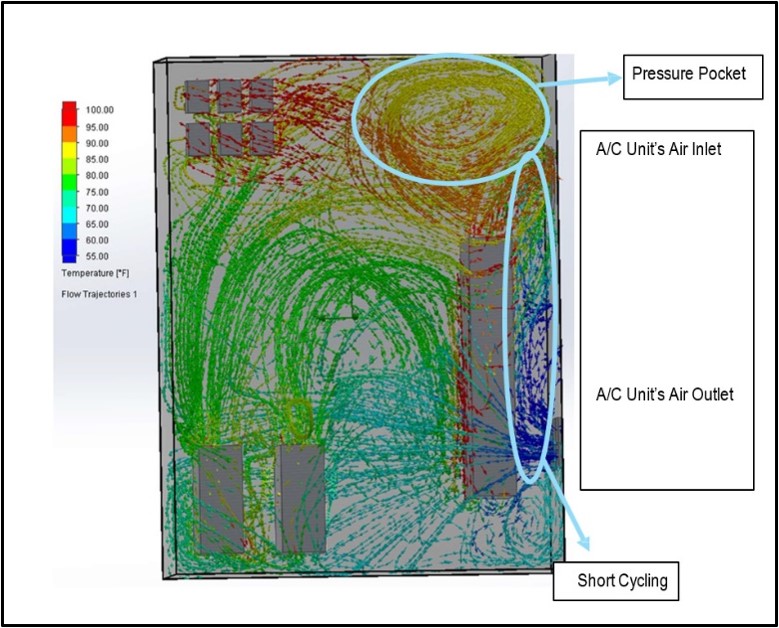
Read the airflow path, not only the thermometer
Heat-producing devices need clear intake and exhaust paths. Spacing, enclosure geometry, fan direction, and nearby obstructions determine whether cooler air reaches a PLC or whether VFD exhaust circles back through the cabinet.
The illustration is a thermal-analysis example, not a universal panel layout. Final clearances and mounting orientation must follow the installed equipment manufacturers.
Plan for year-round thermal management
Outdoor municipal panels may see high summer ambient temperatures plus direct sunlight, so cooling must be evaluated at the location's realistic worst case. Ventilation cannot produce an internal temperature below the incoming air temperature, and both heat-exchanger and air-conditioner performance must be checked at the actual indoor and outdoor conditions.
Winter introduces a different limit. PLCs, displays, batteries, drives, and other devices may have minimum operating temperatures. A thermostatically controlled enclosure heater can keep equipment above those limits and reduce the risk of condensation during cold starts or rapid weather changes.
Heating and cooling controls should be coordinated so they do not fight each other. Setpoints, dead bands, alarms, drain or condensate provisions, and seasonal maintenance all belong in one thermal plan that covers the complete operating environment.
Choose the method that matches the physics
| Method | Good fit | Main limitation |
|---|---|---|
| Passive surface dissipation | Low heat load, adequate exposed area, and ambient temperature safely below the allowable internal temperature | Capacity is limited and strongly affected by cabinet size, mounting, and ambient conditions |
| Filtered ventilation | Clean ambient air that is cooler than the desired panel temperature | Cannot cool below ambient and introduces outside air; filters add maintenance and airflow resistance |
| Air-to-air heat exchanger | Dirty ambient conditions where outside air is cooler than the desired panel temperature and closed-loop separation is needed | Performance depends on temperature difference; it cannot provide refrigeration below ambient |
| Enclosure air conditioner | High ambient temperature, need for below-ambient cooling, or a sealed recirculating air path | Requires condensate, power, mounting, and maintenance planning; actual capacity changes with rating conditions |
| Air-to-water heat exchanger | High heat loads where suitable plant water is available and room heat rejection is undesirable | Requires acceptable water quality, temperature, flow, piping, and leak-risk planning |
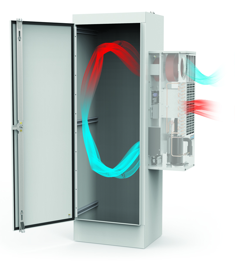
A practical decision boundary
If the maximum ambient temperature is already at or above the desired internal temperature, a fan or air-to-air heat exchanger does not have the temperature difference needed to solve the problem. Refrigerated or water-based cooling may be required.
If ambient air is cool enough but contaminated, a closed-loop heat exchanger may reject heat without bringing that contamination into the cabinet. Final selection should use performance data at the actual internal and external temperatures.
Practical checks before releasing the panel design
Verify the numbers
- Use manufacturer heat-loss data at expected load.
- Include simultaneous duty and future additions.
- Check cooling ratings at actual operating conditions.
Verify the airflow
- Keep inlets and outlets clear.
- Separate supply and return paths.
- Do not direct one device's hot exhaust into another device's inlet.
Verify the environment
- Document heat, cold, humidity, dust, oil, washdown, altitude, and sun exposure.
- Protect the required enclosure rating.
- Consider condensation during cooling, cold starts, and shutdowns.
Verify maintainability
- Provide access to filters and heat exchangers.
- Monitor high temperature or cooling failure where downtime matters.
- Put filter, coil, heater, and thermostat checks into preventive maintenance.
How can BEA help?
BEA can help municipal and industrial teams review component losses, enclosure construction, ambient conditions, airflow paths, and cooling options before heat becomes a reliability problem. For new designs or recurring high-temperature faults, we can help turn equipment data and field measurements into an application-specific thermal-management plan.